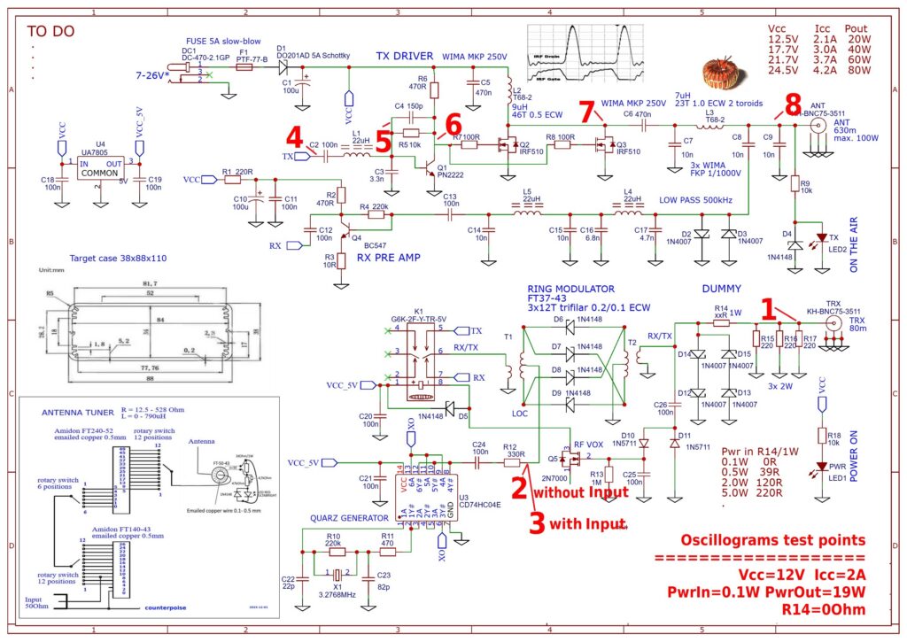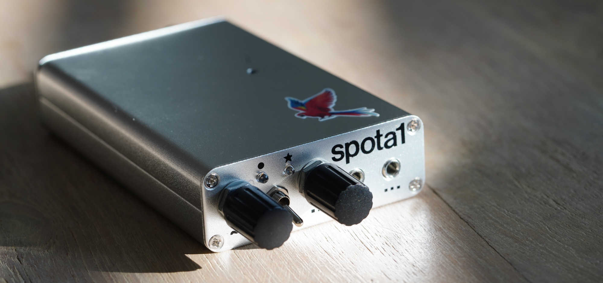

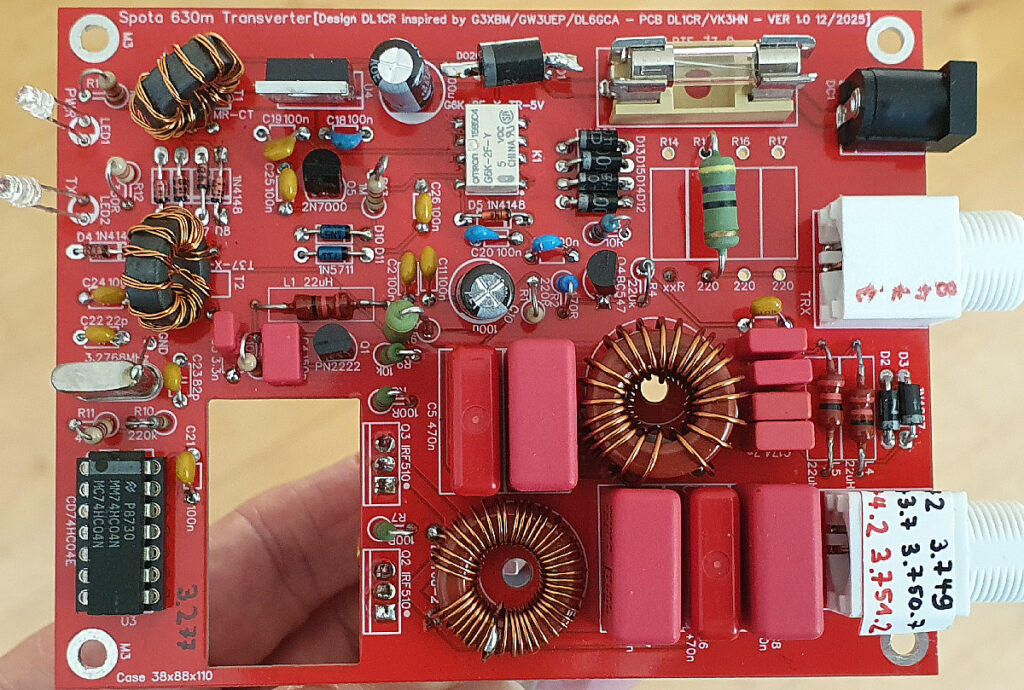
The PCB was designed using EasyEDA and manufactured by JLCPCB. Those in the know can download the schematic and order the pcb here https://oshwlab.com/dl1cr/spotaone1_copy
The transverter for the 630m band receives and generates signals in the 472–479 kHz range. It connects to an 80m transceiver operating between 3.74898 MHz and 3.75598 MHz with an output power of 100 mW to 5 W. The specific, non-round frequency values result from the use of a standard, cost-effective quartz crystal.
Output power depends on the operating voltage: approximately 20 W at 12.5 V and up to 80 W at a maximum of 24.5 V; efficiency is around 80%. Operation at up to 50 W using 20 V (five LiPo batteries) is recommended.
The circuit is assembled on an 83 mm x 108 mm PCB. A finned heatsink of the same dimensions should suffice for a maximum output of 50 W in CW mode (intermittent transmission).
There is no protection circuitry other than a fuse. Although the IRF510 MOSFETs used are very robust, it is strongly recommended to monitor current draw relative to the operating voltage (see schematic, top right). For instance, if the current is approximately 2.1 A at 12.5 V, the antenna matching (SWR) is correct. This eliminates the need for an external SWR meter and prevents excessive current during tuning.
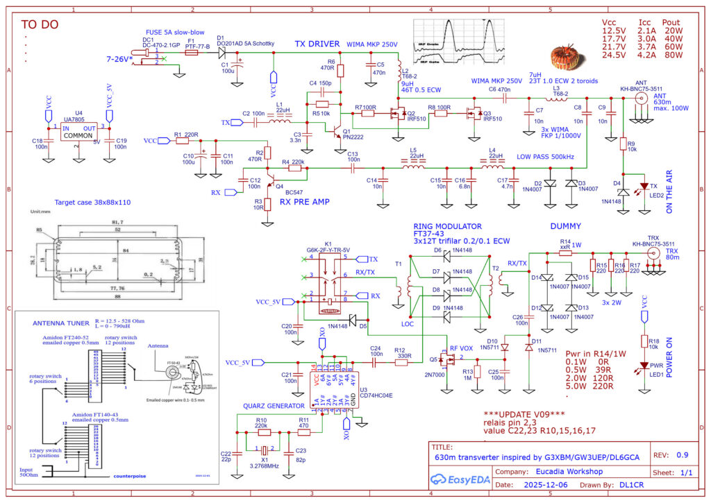
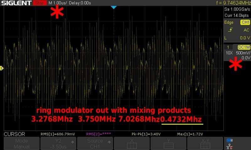
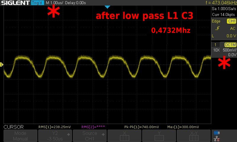
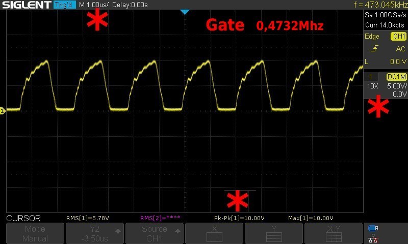
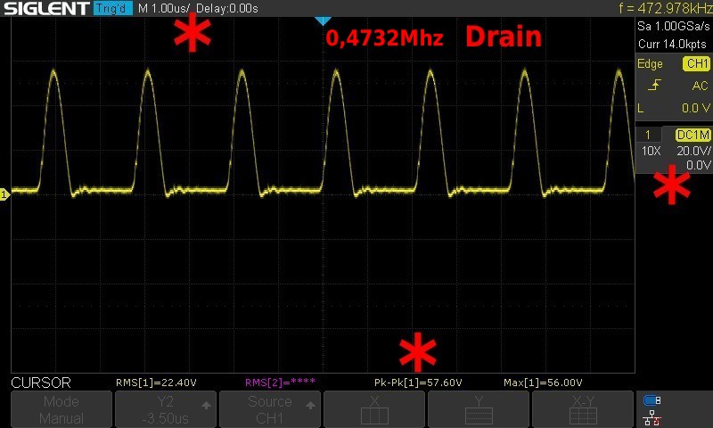
At the end of the blog, a detailed presentation of the oscillograms for the measurement points follows, intended for understanding the circuit, the detection of faulty component placement and solder joints.
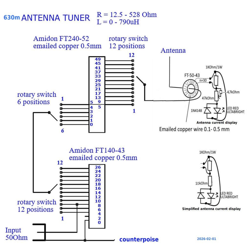
The antenna tuner designed for a classic vertical antenna—10–20 meters long and, ideally, top-loaded—consists of a switchable loading coil wound on a toroidal core and a variable impedance matching circuit. While Amidon’s T52 material is an unconventional choice, a proven alternative involves using two stacked T2 cores with significantly more turns. An LED indicates the antenna current. The entire design is kept as simple as possible for portable operation.
I have explained the theoretical background of shortened vertical antennas for the medium-wave range in several video clips. Unfortunately, they are only in German.
Adjusting a 630m antenna part 1
https://www.youtube.com/watch?v=rTx0S7aGHkI
Adjusting a 630m antenna part 2
https://www.youtube.com/watch?v=N7RYXJmJKos
Adjusting a 630m antenna part 3
https://www.youtube.com/watch?v=2GstSbuuSIo
******************* Measurement Setup for Debugging **********************************
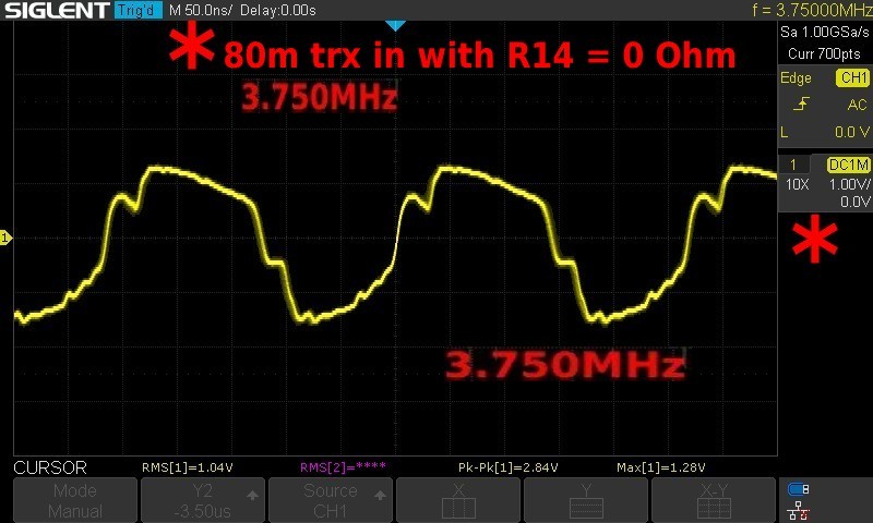
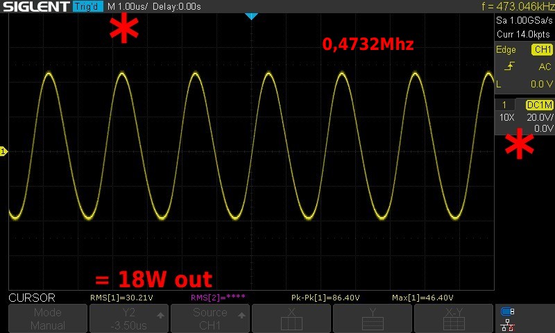
Input 0.1W at 3.70MHz (except for Picture 2)
Output approximately 20W at 472kHz
Ucc 12V; Icc 2A
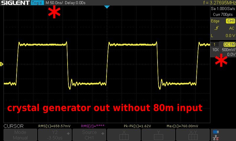
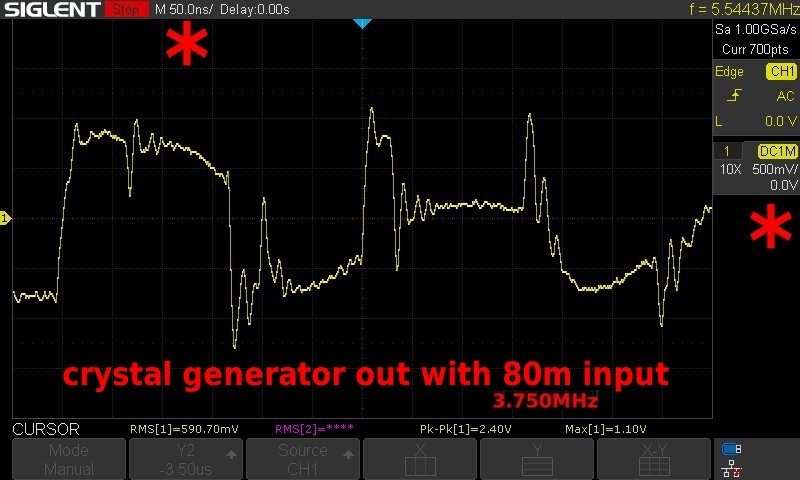
The circuit diagram shows the measurement points, the corresponding pictures show the oscillograms.
At the measurement points 3 and 4, a chaotic superposition of different curves appears. The pictures show a snapshot from a digital oscilloscope with the stop button pressed.
Always note the scale of the time and voltage axes.
Good luck with the troubleshooting.